
SHED CREATIONS:
CO-HAMMER
Tom Woodburn | Chris Turner | Pilar Zhang Qiu
With the continuous increase in life expectancy and an ageing population, there is a need for more senior-friendly products. This requires the creation of devices to complete daily tasks but also to keep on with their passions.
Ethnographic research showed that elderly people are craving independence. DIY tasks often require manual hand tools, such as hammers, that exclude this user group. Not only does this turn DIY into an ordeal, but the repetitive hitting motion of hammers cause strain in muscles and joints, causing injuries that at their age are slow to heal.
Inspired by the 'Men's Shed' branch in Camden Town, we conceptualised and prototyped the first model of a line of tools named after them. The objective: to prove that age is only a number.


DESIGNING FOR
AN AGEING POPULATION
UK's population is ageing. Thanks to advances in technology and
healthcare, the life expectancy of its citizens are increasing. Experts suggest that
in 2036 the proportion of adults over 65 will nearly match that of younger
generations (age 18-64).
Therefore, it is only normal for us to start designing for future generations, aka:
the elderly population, to help them and us maintain our independecy no
matter the age.
Randall, M. (2017). Overview of the UK population - Office for National Statistics. [online] Ons.gov.uk. Available at: https://www.ons.gov.uk/peoplepopulationandcommunity/populationandmigration/populationestimates/articles/overviewoftheukpopulation/july2017
[Accessed 3 Jun. 2018].
01 TIMELINE
INITIAL STEPS
- Inclusive User
Group Selection
- Initial Interviews
- Market Research
- Ideation
- Concept Selection
FURTHER USER RESEARCH
- Interviews
- User Observations
- Insights and Main
Desired Functions
PROTOTYPING 02:
CASING
- Casing Internal Design
- Ergonomics and
External Deign (User
Research)
- 3D Printed Prototype
- Testing and Iterations
- Technical Drawings
TECHNICAL
ANALYSIS
- Donor Product
Teardown
- Product Performance
Requirements
- QFD
PROTOTYPING 01:
MECHANISM
- Internal Mechanism
Design
- Manufacturing
- Testing and Iterations
- Technical Drawings

02 JOURNEY TO THE FINAL PROTOTYPE :
THE IMPORTANCE OF ITERATION
There is nothing such as a perfect first prototype. Iterations are not only normal but necessary. In this project, we generated and ran multiple tests and prototypes to polish the final design of a senior-friendly auto-hammer.
The main areas of work were:

ORIGINAL SHAFT
-
Length - 60 mm
-
Diameter - 9x6 mm (hollow)
-
Hammerhead - None
-
Stroke Length - 13mm
-
Crown Guide:
2 solid walls
(Original rotation to
linear movement)
PROTOTYPE 1 - ALUMINIUM SHAFT
-
Length - 75 mm
-
Diameter - 9x4 mm (hollow)
-
Hammerhead - 20⌀ x 15 mm
-
Stroke Length - 13mm
-
Crown Guide:
1st Trial - 1 wall missing
2nd Trial - 1.5 walls missing
(See p. 25 in PDF)
PROTOTYPE 2 -
EN1A STEEL SHAFT
-
Length - 86 mm
-
Diameter - 8 mm (solid)
-
Hammerhead - 20⌀ x 18 mm
-
Stroke Length - 13mm
-
Crown Guide:
1.5 walls missing
(See p. 25 in PDF)
1 ) INTERNAL MECHANISM | EFFICIENCY
The donor product from which the internal mechanism was developed is a handheld FERM jigsaw.
As the impact generated by the jigsaw was not powerful enough to hammer a nail, it was decided that the main shaft had to be
redesigned.
For a more stable motion, a compressed spring was
introduced at the back of the output shaft. This would deliver
a nonlinear spring-loaded motion. The shaft moves slowly
backwards as the crown guide compresses the spring against the ¼ wall (see p. 25). As the crown gear rotates the crown guide slips past the wall. Then, the compressed spring releases, accelerating the output shaft forward toward the nail. This blow is more impactful and increases dampening.
However, when running the nailing tests (see videos below), the impact generated by the 1st prototype was still insufficient. Therefore, the lightweight aluminium was replaced by an EN1A steel shaft. Its significantly heavier weight increases its momentum as it accelerates to the nail. The performance also improved when adding a spring with an increased spring constant of 13.63 N/m. (See p. 8-10)
For more information: See p.6 in the PDF.


2 ) NAIL HOLDER | INTUITIVE DESIGN
Throughout our user research journey, the need for a nail holder feature became obvious. Up to three different designs were prototyped and iterated.
While prototyping the first concept (see video 03 above), we found out that the nail holder:
-
Did not let the hammerhead fully nail the nail down
-
Was obstructing vision
Although the second concept (D2) enabled the user to see the nail while operating the device, it still did not fully nail it.
This issue was solved in the third concept (D3), with a unique design that retracts as the nail further sinks into the wood.
For more information: See p.12 in the PDF.
3 ) CASING | ERGONOMICS
After asking the Camden´s Shed members to try the blue foam models, we decided to stick to the traditional T-shaped or gun casing design.
During our third visit, 3D printed models were brought to the shed. The main feedback received concerning the ergonomics of the Co-hammer were:
-
Thinner casing body
-
A larger trigger switch would give them more control
-
An anti-slippery material (in turquoise) on the top 'hand resting area' would provide a better grip
For more information: See p.13-17 in the PDF.


 |
|---|
 |
D2
D3
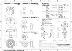
03 TECHNICAL DRAWING SUITE
For more information, access p. 18-30 in the report
 |  |  |  |
|---|---|---|---|
 |  |  |  |
 |  |  |  |